Knowledge center
How to Upload and Process Your 3D Model
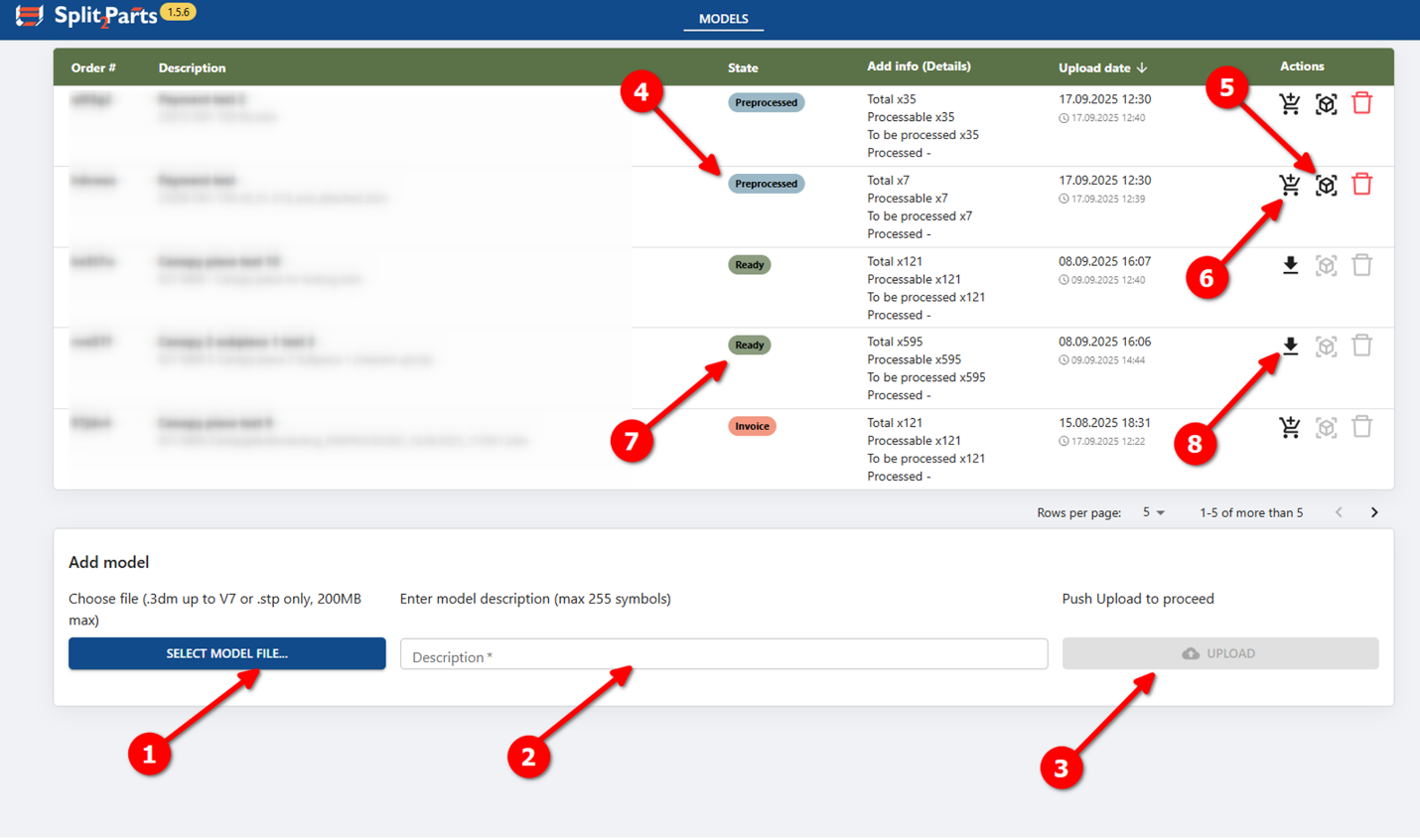
- Prepare your file
Select a file with your 3D model. The model must meet these requirements:- Supported formats: .step / .stp or .3dm (Rhino 7)
- Maximum file size: 60 MB
- Maximum number of objects: 200
- Public alpha limitation: only plate parts are supported
(flat or bent plates, no machining such as chamfers, bevels, blind holes) - Plate parts must be solid objects or closed polysurfaces
(other object types will be ignored) - Do not include profiles such as circular or rectangular tubes, flat bulbs - these may be detected as plates and processed incorrectly
- Add a description
Enter a short description of your model. - Upload the model
Click Upload.
After upload, the model automatically enters the Preprocessing stage, where it is checked and prepared.
During preprocessing:- If the model contains more than 200 objects, processing stops automatically
- All objects except solids and closed polysurfaces are removed
- Plate parts are detected, and their thickness is measured
- Wait for preprocessing
The model status will change to Preprocessed.
This may take from 5 minutes up to several hours, depending on model size and complexity. - Review the model (optional)
Once preprocessing is complete:- A 3D model view becomes available in your browser
- You can inspect the model and adjust part attributes if needed
(this step is optional)
- Purchase and start processing
When the model is ready:- Click Purchase
- Complete payment
(in public alpha, a fixed price applies)
- Wait for processing
Model processing can take 30 minutes up to 24 hours, depending on complexity.
When finished, the model status will change to Ready. - Download results
When the status is Ready:- The Purchase button is replaced by Download Contours
- Click it to download a ZIP package containing:
- .DXF contours, sorted by material and thickness
- .STP files for individual parts, also sorted by material and thickness
3D viewer window layout:
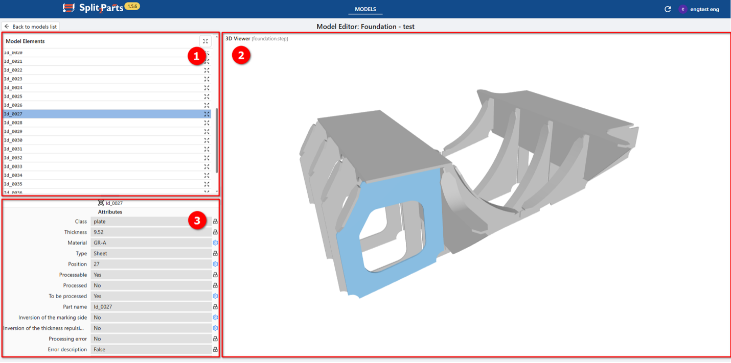
3D Viewer Layout
The viewer consists of three main areas:
- Model Elements List
- Shows all detected parts
- Click a part to:
- highlight it in the 3D view
- display its attributes
- 3D Viewer
- Displays the cleaned-up 3D model
(invalid objects such as lines or non-solids are removed) - You can rotate, zoom, and pan the model
- Clicking a part highlights it and shows its attributes
- Displays the cleaned-up 3D model
- Attributes Panel
Shows attributes of the selected part.- Editable attributes → marked with a blue gear icon
- Read-only attributes → marked with a grey lock icon
Part Attributes (Key Parameters)
- Class (read-only)
Part category (plate, profile, machined part, cast part, etc.) - Thickness (read-only)
Plate thickness (defined automatically during preprocessing) - Material (editable)
Default is GR-A, can be changed manually (text input) - Type (read-only)
Part type (sheet, L-profile, HP, tube, etc.) - Position (editable)
Position number shown near marking lines on connected parts - Processable (read-only)
Indicates whether the part can be processed - Processed (read-only)
Shows whether the part has already been processed
(always No in the 3D viewer) - To be processed (editable)
Controls whether the part will be processed (Yes/No) - Part name (read-only)
System-generated ID + original object name (if available) - Invert marking side (editable)
Use markings from another side of a plate
Note: in public alpha, contours are generated for both sides - Invert thickness repulsion side (editable)
Controls which side of the plate leaves marking lines
Note: in public alpha, mould side preview is not available
Current Limitations (Public Alpha):
Only plate parts are processed correctly.
A valid plate part must:
- be a solid or closed polysurface
- be flat or bent with straight edges (without chamfers, bevels)
- have no blind or stepped holes, other machining
- be symmetric relative to the neutral surface
- have side surfaces connected tangentially
Parts that do not meet these requirements may be processed incorrectly.
Model File Naming Rules For Position Number Generation
This help section explains how to correctly name your model files so the system can automatically assign position numbers to parts without manual editing.
What Is This For?
When you upload a model file (.3dm, .stp, .step), the system analyzes its file name.
You can include special commands directly in the file name to control:
- how part position numbers are generated;
- whether numbers come from object names, layer names, or auto-numbering;
- whether prefixes are added, replaced, or removed.
All commands are removed automatically after processing.
File Name Structure
<BaseModelName> [Commands].<extension>
[Commands] block is optional.
Example
BN-BLOCK_N-ASSEMBLY_N UseLayerAsPosNo StartPosNo=99 PosNoPrefix=Delete.3dm
Explanation
| Part | Meaning |
| BN-BLOCK_N-ASSEMBLY_N | Base model name |
| UseLayerAsPosNo | Use layer name as position number |
| StartPosNo=99 | Starting number for auto-numbering |
| PosNoPrefix=Delete | Remove existing prefix |
| .3dm | File extension |
Separators You Can Use
Commands can be separated using:
- space
- _ (single underscore)
- __ (double underscore)
All options are equivalent and can be mixed.
Examples
- BN-BLOCK_N-ASSEMBLY_N UseLayerAsPosNo
- BN-BLOCK_N-ASSEMBLY_N_UseLayerAsPosNo
- BN-BLOCK_N-ASSEMBLY_N__UseLayerAsPosNo StartPosNo=99
- BN-BLOCK_N-ASSEMBLY_N_UseLayerAsPosNo__StartPosNo=99
Available Commands
1. StartPosNo=<integer>
Sets the starting position number for automatic numbering.
- Must be an integer
- Default value: 1
Examples
- StartPosNo=1
- StartPosNo=25
- StartPosNo=100
Invalid
- StartPosNo=1.5
- StartPosNo=ABC
2. UseNameAsPosNo
Uses the object name from the CAD model as the position number.
- No parameters
- Boolean flag
UseNameAsPosNo
3. UseLayerAsPosNo
Uses the layer name as the position number. In this case, each part shall be on individual layer.
- No parameters
- Boolean flag
UseLayerAsPosNo
⚠️ Important
You cannot use UseNameAsPosNo and UseLayerAsPosNo together.
4. PosNoPrefix=<string>
Controls prefixes for position numbers.
- No spaces allowed
- Any characters are allowed
- Special value Delete removes an existing prefix
Examples
Add a prefix:
- PosNoPrefix=AX
- PosNoPrefix=P-
Remove existing prefix:
- PosNoPrefix=Delete
If omitted, no prefix is applied.
Position Numbering Modes
1. Automatic Numbering (Default)
BN-BLOCK_N-ASSEMBLY_N.3dm
Result:
- BN-BLOCK_N-ASSEMBLY_N-0001
- BN-BLOCK_N-ASSEMBLY_N-0002
2. Automatic Numbering with Custom Start
BN-BLOCK_N-ASSEMBLY_N StartPosNo=100.3dm
Result:
- BN-BLOCK_N-ASSEMBLY_N-0100
- BN-BLOCK_N-ASSEMBLY_N-0101
3. Automatic Numbering with Prefix
BN-BLOCK_N-ASSEMBLY_N PosNoPrefix=CP.3dm
Result:
- BN-BLOCK_N-ASSEMBLY_N-CP0001
4. Use Object Name as Position Number
a. Using full object name:
Object name in model: CP7
BN-BLOCK_N-ASSEMBLY_N UseNameAsPosNo.3dm
Result:
- BN-BLOCK_N-ASSEMBLY_N-CP0007
b. Remove original prefix:
BN-BLOCK_N-ASSEMBLY_N UseNameAsPosNo PosNoPrefix=Delete.3dm
Result:
- BN-BLOCK_N-ASSEMBLY_N-0007
c. Replace prefix:
BN-BLOCK_N-ASSEMBLY_N UseNameAsPosNo PosNoPrefix=AX.3dm
Result:
- BN-BLOCK_N-ASSEMBLY_N-AX0007
5. Use Layer Name as Position Number
Works exactly like name-based numbering but uses layer names instead.
BN-BLOCK_N-ASSEMBLY_N UseLayerAsPosNo.3dm
Invalid File Names (Processing Will Fail)
| Problem | Example |
| Two position sources | UseNameAsPosNo UseLayerAsPosNo |
| Non-integer start number | StartPosNo=1.5 |
| Invalid start number | StartPosNo=ABC |
| Unsupported extension | Any format except .3dm, .stp, .step |
Best Practices
- Use any separator you prefer: space, _, or __
- Command order does not matter
- Use PosNoPrefix=Delete to explicitly reset prefixes
- Keep the base model name clear and readable